Phaser 203


DESCRIPTION OF CONTROL KNOB FUNCTIONS OF THE 203 SYNTON PHASER
PRESET LFO
Controls oscillation frequency of the LFO between approximately 0.05 Hz and 10 Hz.
ENV LFO
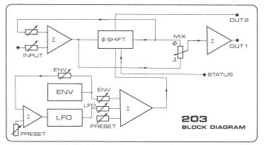
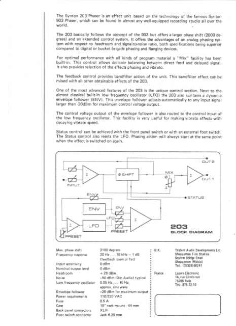
This control knob is for applying the output contro1 voltage of the envelope follower (ENV) to the control input of the low frequency oscillator (LFO). This facility is useful for decreasing the LFO modulation speed in accordance with the audio input level. Application: changing vibrato speed on decaying tones of a musical instrument.
PRESET MOD
This control is for setting the range of modulation by the LFO or
the ENV. For a maximum phase shift the knob should be turned fully clockwise to HF. If the modulation effect has to be applied to audio program with lower-frequencies, it can be useful to alter the control range by turning the knob more in the LF direction.
LFO MOD
This controls the output voltage of the LFO. The amount of phase shift by the LFO is dependent on the setting of this knob.
ENV MOD
The phase shift caused by the output of the envelope follower can be adjusted between zero and maximum withthis control knob. The LED in the MODsection is monitoring the speed and depth of the LFO and ENV control effects.
STATUS 1/0
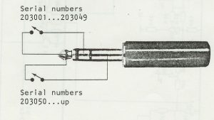
This switch provides click free switching on the effects of the 203. The SWITCH Jack input can be useful for connecting a footswitch to the unit. (See note). The STATUS switch also resets the LFO, so that when switched on, the effects always will start at the same point.
INPUT 1/0
Input attenuator. Only to be used when the input signal should exceed + 6dBmor when the FEEDBACKcontrol is used.
FEEDBACK.1/0
With this knob feedback isadded to the phaser system for making typical band filter effects. It can be used on both phasing or vibrato effects. Turning up this control will cause higher gain within the pass band of the system, which might also cause distortion. In that case it is necessary to reduce the input signal by turning the INPUT knob down.
MIX I/O
This knob is for adjusting the optimal effect. Here the direct signal is mixed with the delayed signal, for making the typical phasing effect, which should occur with the knob about halfway can be useful for simulating doppler
or vibrato effects.
INPUT
XLR on back panel. Accepts normal signal levels (0 dBm). See technical data.
OUTPUT 1
XLR on back panel. Phasing output.for all effects.
OUTPUT2
XLR on back panel. This output only gives the band filter effect when the FEEDBACK control is used.
It can be very useful to simulate stereo effects when it is used together with input 1.
POWERSUPPLY
Power requirements are 220 VAC normally Other mains voltages on request.


